Availability View
StateUse controller state and active alarms to prioritize a local check. “Ready” confirms controller status, not fuel quality, ventilation clearance or the absence of leakage.
Verify against the site inspection record.

Connected monitoring is valuable when a controller event reaches the right person with enough context to decide what happens next. The operating model below links generator state, transfer events, runtime and service evidence without presenting connectivity as a substitute for field inspection.
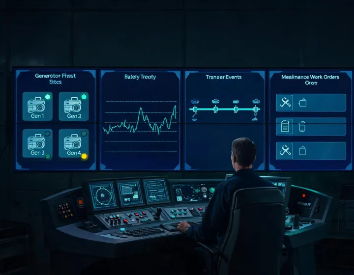
Use controller state and active alarms to prioritize a local check. “Ready” confirms controller status, not fuel quality, ventilation clearance or the absence of leakage.
Compare event timestamps with the defined ATS sequence. Unexpected delay can originate in sensing, start conditions, load acceptance or transfer equipment.
Battery voltage and charger events can identify a reason to inspect, but temperature, connection condition and an appropriate load test remain relevant.
Combine operating hours with scheduled intervals and field observations. A completed exercise is not equivalent to a completed maintenance inspection.
A useful dashboard exposes its assumptions. These review packages help a contractor or facility team determine whether a displayed status corresponds to the installed control sequence and service practice.
Identify available controller interfaces, network path, data ownership, alarm recipients and conditions that still require local observation.
Generate permitted test events and confirm timestamp, transmission, receipt, acknowledgement and work-order routing under documented conditions.
Use recurring battery, runtime or fault patterns as inspection prompts. Avoid treating a trend as a diagnosis until a qualified field check confirms the cause.
Periodically audit user access, notification destinations, communication failures and record retention under the organization’s cybersecurity policy.
Technical limits: remote monitoring depends on controller compatibility and network availability; predictive rules can produce false positives or miss mechanical conditions not represented by a sensor; cybersecurity responsibility spans device configuration, credentials, network segmentation and organizational policy. Local code, equipment manuals and qualified service procedures remain controlling references.
Start with the controller model, ATS arrangement, available communications and current service workflow.
Request a Monitoring Architecture Review